![]()
|
2022-3-29 test run 2 |
曲がってしまったコンロッドの作りなおしだけでなく、その原因と対策、その他細かい調整などがあり、時間がたってしまいました。
今回は最後にリア―シリンダ―単気筒での回転の状況をアップできるまでこぎつけました。(フロントシリンダーも回りましたが動画を取り損ねました)
いろいろ盛りだくさんですがご覧ください。
なお今回は英文はDeepLと言う自動翻訳アプリを利用してみました。私の英語力よりこちらのほうが上ですね。
It took a long time not only to rebuild the bent connecting rods, but also to find the cause of the problem, take countermeasures, and make other minor adjustments.
This time, we finally managed to upload the status of the rotation of the rear cylinder in a single cylinder. (The front cylinder also rotated, but I failed to get a video of it.)
There is a lot going on, but please take a look.
This time, I used an automatic translation application called DeepL to translate the English text.
This English is better than mine.
今回は7075の端材がありましたのでこれで作ります。 Cutting out the material. In this case, we had a scrap piece of 7075, so we used it to make this. |
Cutting to thickness as per drawing |
We are boring the big end section. |
External profile cutting. |
CNCを使えばいいのですが、表裏両面をきっちり位置合わせが難しくて手作業でやりました。 Arc cutting. I could have used a CNC, but it was difficult to align the front and back sides exactly, so I had to do it by hand. |
Cutting the center section. |
The finished connecting rod and gasket. |
The gasket was made by CNC cutting. |
Photo of cutting in progress. |
エンドミルが切れなくなっているのでしょう、細かいバリが出ます。 Cutting is finished. The end mill is probably no longer sharp, and fine burrs appear. |
| モーターをゆっくり回す必要があるので電圧監視回路を作りました。その材料です。 ちなみに激安と称して売られている安定化電源を買うのと同じくらいの費用がかかってしまいました。 The next step is to adjust the transistor ignition module. We need to turn the motor slowly, so we made a voltage monitoring circuit. Here are the materials. By the way, it cost me as much as buying a stabilized power supply that is sold as very cheap. |
| 電流もモニターできます。 モーターはやっと回る最低の電圧0..9Ⅴ位で250rpmくらいまわってしまいます。1Ⅴになるともう1000rpm。 エンジンは2回転で一回火花が飛びますので、エンジン回転数としては500、2000rpmの相当します。 250rpmで火花が飛ばなくてはなりません。 This is how it was made. The current can also be monitored. The motor will run at 250 rpm at the lowest voltage of 0.9 V. At 1 V, it will run at 1,000 rpm. The engine sparks once every two revolutions, which is equivalent to 500 or 2000 rpm. The spark must fly(ignite) at 250 rpm. |
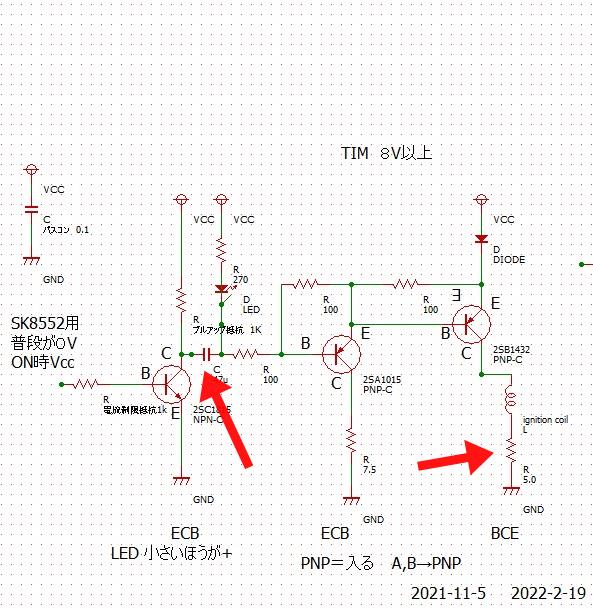
 今までの回路では直流から動作しましたが、ホールセンサー上でマグネットが止まるとイグニションコイルの一次側に4A位電流が流れてしまいます。この電流だと一次コイルに熱が出てパラフィンが解け、二次回路に変形が起き巻き線が切断して、コイルがだめになります。 今までの回路では直流から動作しましたが、ホールセンサー上でマグネットが止まるとイグニションコイルの一次側に4A位電流が流れてしまいます。この電流だと一次コイルに熱が出てパラフィンが解け、二次回路に変形が起き巻き線が切断して、コイルがだめになります。コイル巻きは結構大変です。 そしてテストラン中はホールセンサー上でマグネットが止まっていてもほかのことに気をとられ見落としてしまいがちです。回るか回らないかの瀬戸際ですので、少しでも安定して火花を飛ばしたいため工夫をしました。 赤矢印の部分、47マイクロのセラミックコンデンサーを追加しました。これで直流はカットできます。 さらに一次コイルと直列に電流制限抵抗も入れました。 動作電圧10Vで抵抗は5Ωなので2A以上は流れません。 これでエンジンがどのタイミングで止まっていてもコイルの破壊からは守れます。 The circuit so far has operated from DC, but when the magnet stops on the Hall sensor, a current of about 4A flows in the primary side of the ignition coil. With this current, heat is generated in the primary coil, the paraffin melts, deformation occurs in the secondary circuit, the winding breaks, and the coil is ruined. Coil winding is quite difficult. And during the test run, even if the magnet stops on the Hall sensor, it is easy to overlook it because you are preoccupied with other things. Since the magnet is on the verge of turning or not turning, we devised a way to make the spark fly as stably as possible. I added a 47-micro ceramic capacitor to the red-arrow part. This will cut the DC current. I also added a current limiting resistor in series with the primary coil. The operating voltage is 10V and the resistor is 5Ω, so no more than 2A can flow. This will protect the coil from destruction no matter when the engine is stopped. |
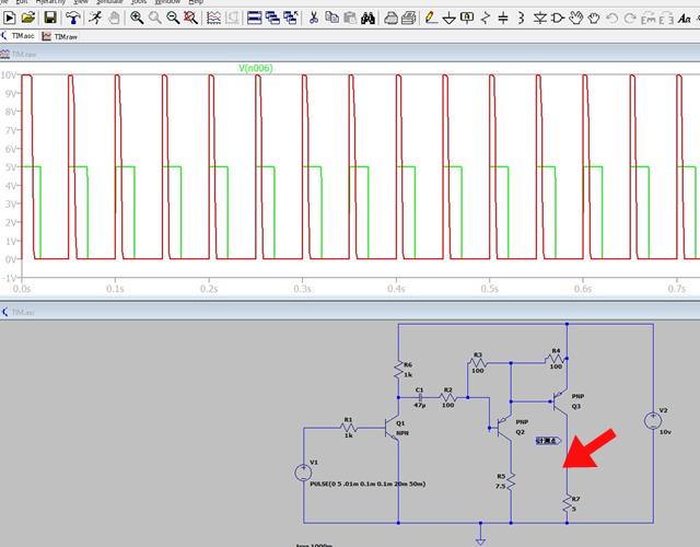
 今回アナログデバイセス社が無料で公開している回路シミュレータLT-spiceと言うアプリを使ってみました。 今回アナログデバイセス社が無料で公開している回路シミュレータLT-spiceと言うアプリを使ってみました。回路のいろいろの条件のパルスを入れ、出力も見られます。 部品の値も簡単に変えられます。 ただ一点今回の回路ではコイルのインダクタンスがわかりません。 インダクタンスメーターを買えばいいのですがコイルを何個か買えるくらいの値段はします。 と言うことでコイル抜きで電流制限抵抗部での出力を見ました。 緑線が入力パルスです。パルス幅は50msにしてあります。1000/50=20 20回/secのパルスです。20X60=1200rpm かなり電気的にはゆっくりなのですが エンジン上では2400rpm相当でかなり高速です。 実際の回路上でも試して47マイクロなら大丈夫と判断しました。 赤矢印が測定点です This time I used an application called LT-spice, a free circuit simulator published by Analog Devices. You can input pulses for various conditions of the circuit and see the output. You can also easily change the values of the components. The only thing is that I don't know the inductance of the coil in this circuit. You can buy an inductance meter, but it is expensive enough to hold several coils. So I looked at the output at the current-limiting resistor part without a coil. The green line is the input pulse. Pulse width is set to 50ms. 1000/50=20 20 times/sec pulse. 20X60=1200rpm Although it is very slow electrically On the engine, it is quite fast, equivalent to 2400 rpm. We tested it on the actual circuit and determined that 47 micro is OK. Red arrow show the masuring point. |
| The red arrows indicate the added resistors and capacitors. With aerial wiring, adding components is relatively easy. |
| 上死点がよく分かり、また負荷もかからないようヘッドはつけていません。理論上の発火点と実際の点火が食い違っていないかタイミングライトでもチェックします。 何しろこれがおかしく無ければコンロッドが曲がってしまうなんてことは起きないはずですから・・・ The next step is to check the ignition timing. The head is not attached so that the upper dead point is well understood and no load is applied. A timing light is also used to check for discrepancies between the theoretical ignition point and the actual ignition point. If there is no discrepancy between the theoretical ignition point and the actual ignition point, the connecting rods will not be bent. |
本来マグネットがホールセンサーから離れるとき(緑矢印)に点火するはずなのですが、近づいてくるタイミング(赤矢印)で点火してしまいます。これだとひどいノッキングを起こしていまうでしょう。コンロッドも曲がる。 しかしこれってリア―シリンダ―なのです。 曲がってしまったのはフロントシリンダーのコンロッド。 うーむ それにしてもどうしてこんな位置で点火してしまうのだろう。 The rear cylinder ignition is unusually fast. It should ignite when the magnet leaves the hall sensor (green arrow), but it ignites when it comes closer (red arrow). This would cause severe knocking. The connecting rod is also bent. But this is the rear cylinder. It is the connecting rod of the front cylinder that is bent. Hmmm... Still, how could it ignite in such a position? |
軸は鋼で出来ています。これが磁化していて何か悪さをしている? クリップを近づけてみましたがくっつきせんでした。 少し軸から離れるようなホルダーを作りなおしました。 (上の写真は作りなおしたものをセットして撮影しています、そうでないとマグネットの位置が見えないので) これが良かったのかわかりませんがとにかく離れるときに点火するようにはなりました。 We wondered if the Hall sensor was too close to the central axis. The axis is made of steel. Is this magnetized and doing something wrong? I tried putting a clip close to it but it did not stick. I remade the holder so that it is slightly away from the shaft. (The photo above was taken with the new holder in place, otherwise the position of the magnets would not be visible.) I don't know if this was a good thing, but at any rate, it now ignites when it leaves. |
よく見るとインテークマニフォールド部分がかなり振動します。 ここからエアーが漏れているようです。 もう一つのタイプに付け替えることにしました。 I started a test run. It only turns a few times and then stops. If you look closely, you can see that the intake manifold area vibrates quite a bit. It seems that air is leaking from here. I decided to replace it with another type. |
| あちこち微調整しましたがどうもうまく取り付けできません。 だから上のタイプのものを取り付けたのです。 However, it does not attach properly at the V-shaped valley. I tried fine-tuning here and there, but could not get it to attach properly. So I installed the upper type. |
| 半日苦労してうまく取りつかなかったものが10分もかからずにうまく取りつけできました。 いったん組んであるものをばらすのには勇気が必要ですが早く外すべきでした。つけたままでの作業時間と比べたら1/10以下の時間で作業が完了しました。 I removed both rocker cases, a minute's work, but by this process it made far easier. I was able to successfully install them in less than 10 minutes after struggling for half a day to get them in place. It takes a lot of courage to disassemble something that is already assembled, but I should have taken them off sooner. It took less than 1/10th of the time it would have taken me to do the work with the panel still in place. |
| 燃料パイプから息を吹き込みました。なんと完全に閉じていません。 I turned it further, but it still exploded a few times and then stopped, blowing back a misty mixture from the carb. I thought the mixture was too thick, so I started to squeeze the needle valve tighter and tighter. Finally, I squeezed it all the way down, but the situation remained the same. I blew in through the fuel line. To my surprise, it was not completely closed. |
| そちらはちゃんと絞り込めば完全に閉塞できます。 I happened to have a carb of the same type, so I compared it with that one. The other one can be completely closed if it is properly squeezed. |
| 締まりきらないほうのアイドル調整バルブの中心穴径が閉じ切るもののほうよりわずかに大きいです。 閉じるほうは1.2㎜のドリルシャンクがどうにか入るくらい、だめな法はスカスカ、でも1.3㎜は通らない。わずかですがこの差なんでしょう。 アイドル調整バルブを交換したいのですが外し方がわかりません。そして前回外そうとしたのかスプレーバー側がつぶれてしまっています。 作りなおしを考えましたが、とりあえずニードルバルブホルダーを交換してみました。きっちり閉じます。 これでキャブもOK。 I removed the needle valve holder. The center hole diameter of the idle adjustment valve of the one that does not tighten is slightly larger than the one that closes off. The one that closes can somehow fit a 1.2mm drill shank, while the one that doesn't is too small, but 1.3mm can't fit through. It is a slight difference, but I guess this is the difference. I want to replace the idle adjustment valve, but I don't know how to remove it. And the spray bar side is crushed from the last time I tried to remove it. I thought about rebuilding it, but I replaced the needle valve holder for now. It closes tightly. Now the carb is OK. |
| 単気筒でのテストランです。 もう一つのシリンダーはプッシュロッドとプラグを外してあり、空回りです。 これならノッキングを起こしてクランクシャフトが曲がってしまうことはないでしょう. はじめに大きく揺れるのは私が三脚にぶつかったためです。 突然止まってしまったように見えますが、イグニションモジュールをオフしての停止です。 This is a test run with a single cylinder. The other cylinder has the pushrod and plug removed and is idling. This will not cause knocking and bend the crankshaft! The first big jolt is my hitting the tripod. It looks like the camera suddenly stopped, but it did so by turning off the ignition module. |
There is no particular meaning. It is a reminder of the throttle opening. |