![]()
2008-11-20 Ignition checker & revolution counter
今回は点火チェッカーとタコメータです。
This time I made ignition checker and revolution counter.
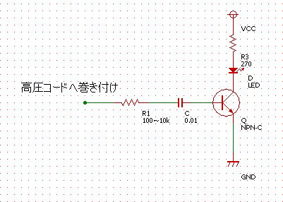 プラグが失火しているかどうかをチェックする回路です。 プラグが失火しているかどうかをチェックする回路です。タイミングライトのストロボをLEDに置き換えただけのものです。 ただしLEDは超高輝度タイプのものでないと発光を視認できません。 (実際のタイミングライトはインバータ、サイリスタなど使いもっと複雑ですが) Ignition checker. I used super high brightness LED. When I used normal LED, I could not see the flash under normal condition. |
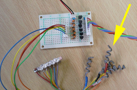 出来たチェッカーです。黄色矢印はピックアップコイル。 点火チェッカーは単一ではうまく作動するのですが、5個並ぶと、ピックアップ部が隣の高圧も拾ってしまったり、止まる寸前の状態はうまく把握できないなどあり没になりました。 Assembled. Yellow arrow shows pick up coil. When it was used isolate, it worked well. But 5were used at once, pick up coil piked up next ignition coil signal. I stopped to use them. |
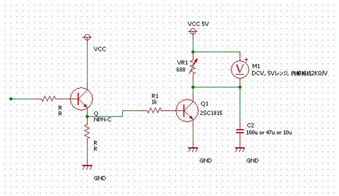 トランジスタによるタコメータ。 トランジスタによるタコメータ。入力はホールICの出力を使いました。 この回路は高回転領域になるにしたがってメータのふれが小さくなると言う欠点がありました。実際に使ってみると迫力に欠けるのでやめにしました。 Revolution counter circuit using transistor. This circuit has the defect that the swing of meter becomes small when the revolution becomes high. I stopped to use it. |
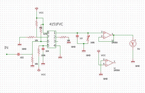 いろいろ検索しましたらf−vコンバータNJM4151という便利なICがありました。この中の一番簡単な回路をそのまま利用しました。ただこの出力は140マイクロAしかありません。そのままではデジタルテスターの電圧計はふれますが内部抵抗5kΩほどのパネルメータはほとんどふれません。オペアンプで増幅しました。 いろいろ検索しましたらf−vコンバータNJM4151という便利なICがありました。この中の一番簡単な回路をそのまま利用しました。ただこの出力は140マイクロAしかありません。そのままではデジタルテスターの電圧計はふれますが内部抵抗5kΩほどのパネルメータはほとんどふれません。オペアンプで増幅しました。これらの回路については細かいことをいろいろioioさんに教えてもらいました。 I found the f-v converter IC, NJM4151. The output of this IC is very small so I had to use operation amplifier LM358. This circuit works well. |
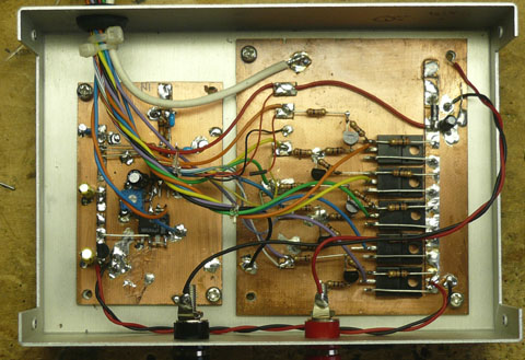 組上がった回路。左半分がタコメータ回路。 組上がった回路。左半分がタコメータ回路。右半分はトランジスタイグニション回路(5個分)です。 Left half is the circuit of revolution counter. Right side is transistor ignition circuit. |
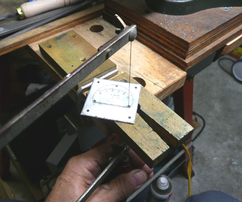 タコメータパネルの製作開始。 タコメータパネルの製作開始。CNCを持っていませんので全て手作業です。 そこそこうまく出来るようになりました。 Making the pannel of revolution counter I have the saw in left hand but I am not left handed I must have camera in right hand. |
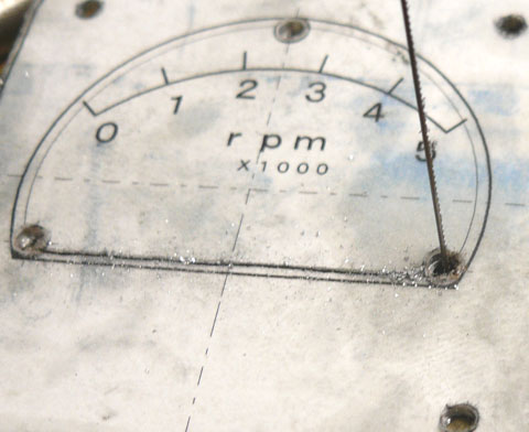 鋸引きは2本ガイドラインを引いてそこからはみ出さないようにするのがうまく行くようです。私はこれでうまく行くようになりました。(たまに失敗しますが) 鋸引きは2本ガイドラインを引いてそこからはみ出さないようにするのがうまく行くようです。私はこれでうまく行くようになりました。(たまに失敗しますが)I cut between lines. I do it well in this method. |
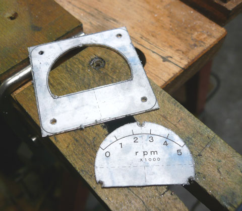 切り抜きが終わりました。 切り抜きが終わりました。あとはひたすらヤスリがけ。 これも固定をしっかりすることでかなりうまく出来るようになりました。 Finished to cut. Then I will do filing. |
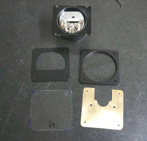 一番上がメータ本体。下の4つが作ったパーツです。 一番上がメータ本体。下の4つが作ったパーツです。Upper is the naked votage meter. Lower 4 are handmade parts. |
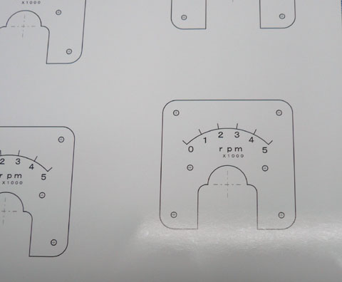 メーターパネル。 メーターパネル。CADで書いて、写真用紙にプリントアウトしました。 CNCがあればアルミ板に刻印出来るのでしょうが。 Panel printed out on the paper for photo print |
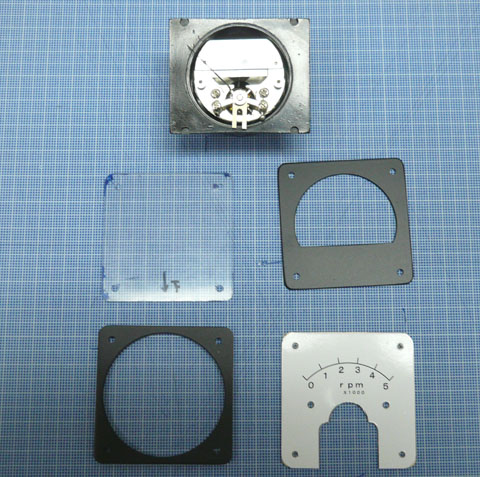 パネルを切り抜いてベースの板に張り付けました。4隅にごくわずか接着剤をつけて貼ってあります。 パネルを切り抜いてベースの板に張り付けました。4隅にごくわずか接着剤をつけて貼ってあります。Panel was glued on the brass panel |
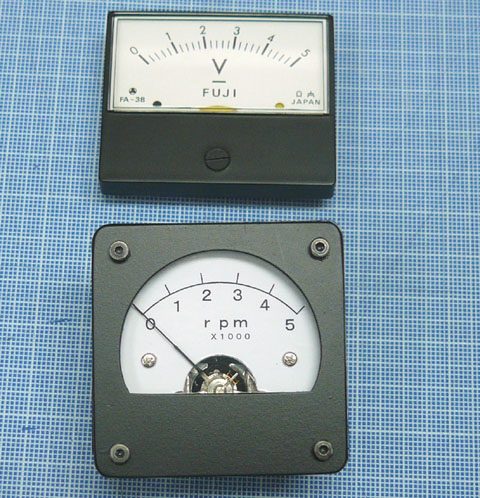 完成。 完成。上がオリジナルです。 計器らしく出来たのではと思っています。 Finished. Upper one is original. Lower is handmade. |