![]()
|
2023-04-18 trouble shooting 6 |
前回の続きです。
エンジンが回るようになり。、精神的余裕ができたため今回からまた英文も添付しました。
この英文はChatGPTで生成してもらいました。
すごい時代になったものです。
Continuing from the last time, the engine started running, and as a result, I was able to have some mental relief. From this time on, I have attached English text again. This text was generated by ChatGPT. It's amazing how far we've come in this era.
コンロッド、フロントシリンダー用のマグネットプレートなどを作りなおし、やっとテスト運転できる段階までこぎつけました。 ここで焦ってすぐに回してしまうとまた思わぬダメージを受けてしまいます。 と言うことでバルブタイミングや点火タイミング、圧縮テストなどを再度チェックしなおすことにしました。 まず初めに圧縮テストをしました。このテストはシリンダーヘッドとバルブ機構が動作していれば確認できますし、これがだめなら他がいくら正常動作していてもエンジンは回りません。 と言うことでコンプレッションテスターをつけてスターターで回してみました。 な、なんと0.3Mpしか出ません。 要するにこれって圧縮ほぼゼロと言うことです。 前回リングを作りなおしてから実質のエンジン回転時間は数分にもならないでしょう。 この時間でリングが摩耗してしまったのでしょうか? リングの再製作を覚悟しました。 しかしもしかするとバルブシート当たりがおかしくなったりしても圧縮は出なくなります。 一応バルブチェッカーでチェックすることにしました。 I have finally managed to rebuild the magnet plates for the connecting rod of front cylinder, and have reached the stage where I can conduct test runs. However, if I rush and turn the engine immediately, I may end up suffering from unexpected damage. Therefore, we I have decided to recheck the valve timing, ignition timing, and compression test. I started with the compression test. This test can confirm whether the cylinder head and valve mechanism are working, and if it fails, the engine will not start even if other components are functioning normally. So I attached a compression tester and tried to start the engine with the starter. However, the reading showed only 0.3 MP. In other words, it means that there is almost no compression. Since I rebuilt the rings last time, the actual engine operating time was only a few minutes. Could the rings have worn out in such a short time? I have prepared ourselves for remaking the rings. However, it is also possible that the compression may not come out even if the valve seat is damaged. Therefore, I have decided to check it with a valve checker, just to be sure. |
バルブチェックをしようにも 赤矢印で示すコネクターからシューシュー音を立ててエアーが漏れてしまいます。 ここはつけ外しが多いところなので壊れてしまったようです。 新品に交換しました。 この時ふと思ったのです。コンプレッションテスターもどこかでもれているのでは・・・と。 I tried using a valve checker, but when I tried to check the valve, air leaked out with a hissing sound from the connector indicated by the red arrow. This part is frequently attached and detached, so it seems to have broken. I replaced it with a new one. At that moment, I suddenly thought that the compression tester might also be leaking somewhere. |
赤矢印のところからリークがありました。 ここを締め直して漏れがなくなったら、圧縮は1MPa出るようになりました。 リングの作りなおしまで覚悟した身にとっては、とてつもない朗報でした。 Bingo! There was a leak from the spot indicated by the red arrow. After tightening it up and stopping the leak, the compression was up to 1 MPa. For me who was prepared to remake the rings, it was fantastic news |
It would be best to measure everything precisely at this point, so I set up a scale plate to determine the timing. |
I also measured the valve timing with a dial gauge. |
すると赤矢印のフロントシリンダーのカムシャフトがマグネットホルダーごと全体で軸方向に前後しているではありませんか。 今まではちょっと振れているかなくらいにしか見ていませんでしたが結構振れています。 Now, thinking it would finally be okay, I started running the motor to break it in. Then I noticed that the camshaft of the front cylinder, indicated by the red arrow, was moving back and forth in the axial direction with the magnet holder. Until now, we had only noticed a slight vibration, but it turns out that it's actually quite significant. |
| 軸方向にかなりあそびが出ています。このままではとても使い物になりません。 ホールICも無反応になってしまっていました。(取り替えました…配線が振動で切れない様接着剤でモールドしてあるので無理やり壊してはがしとるのでなかなか大変でした) When I removed the plate and took a closer look, I noticed that the Hall sensor support had been scratched quite badly, perhaps due to contact. There was a significant amount of play in the axial direction, making it unusable in its current state. The Hall IC was also unresponsive, so I had to replace it. It was quite difficult to remove because it had been molded with adhesive to prevent the wiring from breaking due to vibration. |
| These are spacers we made to prevent vibration. Since I had to cut and try multiple times, I ended up with quite a few. |
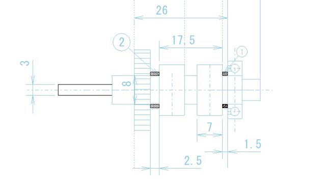
 カットアンドトライなどと言わずに図面をチェックすべきでした。 カットアンドトライなどと言わずに図面をチェックすべきでした。1.5㎜と2.5㎜のスペーサを作れば大丈夫。 無駄な時間を使ってしまい、反省です。 これで軸方向の動きは無くなりました。 これでオーケーかと思い今度は本格的に回してみました。 圧縮もOK,火花もよし、バルブタイミングもよし。点火タイミングもよし。 一発で始動しました、おー、と喜んだのもつかの間。 数回回すとまたかからなくなってしまいました。散発的にバババ程度。 I should have checked the drawings instead of relying on trial and error. If I had made spacers of 1.5mm and 2.5mm, it would have been fine. I wasted time and I regret it. Now there is no axial movement, so I ran the engine again. The compression was good, the sparks were good, the valve timing was good, and the ignition timing was good. It started on the first try, and I was happy, but it didn't last long. After a few runs, it wouldn't start again, only making sporadic noises. |
フロント側のマグネットホルダの軸はリアー側のギアーとの干渉を避けるため3㎜しかありません。 この部分で滑りが出てしまうようです。 This time, I had a feeling that the timing was off. The axle of the magnet holder on the front side is only 3mm to avoid interference with the gear on the rear side. It seems that there is slipping at this point. |
| これではいくらセットスクリューを締めこんでもすべってしまうようです。 3㎜のシャフトに対してM2のセットスクリューではこれだけの直径のものを固定できないようです。 作り替えました。 I have added a 4mm collar to the 3mm shaft, and then added another collar on top of that. I then fixed a base plate to the collars and attached the magnet holder to that plate. However, even if I tighten the set screws as much as possible, it still slips. It seems that the M2 set screws cannot secure an object with such a large diameter on a 3mm shaft. I have made another one. |
CAD上では4.8㎜までは歯車と接触しないですむはずなのですが、4.8とか4.5と言った端数のリーマーを持っていないので4㎜にしました。 そしてこの4㎜のシャフトに固定できる一体型ベースプレートを作りなおしました。 これも最初はm3のセットスクリュー一個で固定していましたがやはり滑りが出てしまい、 3本のセットスクリューで固定するようにしました。その後はすべらなくなりました。 I stopped relying on set screws to secure the 3mm shaft and instead made a 4mm collar with an outer diameter of 4mm and fixed it with Locktite. According to the CAD, the gear should not contact anything up to 4.8mm, but I didn't have a reamer with fractions such as 4.8 or 4.5, so I settled for 4mm. Then, I remade the one-piece base plate that can be fixed to this 4mm shaft. At first, I tried to fix it with a single M3 set screw, but it still slipped, so I used three set screws to secure it. After that, it no longer slips. |
| ここで滑りが出るということは、点火時期が大幅に狂ってしまうということです。 本来の点火時期とは全く違うタイミングで火花が飛ぶ=とんでもないノッキング起きる=コンロッドに力がかかり曲がってしまう。 こんなことが起きていたのでしょうね。 These are plates that are no longer used. If there is slipping here, it
means that the ignition timing is greatly off. The spark will ignite at
a completely different timing than the original ignition timing, causing
severe knocking and putting stress on the connecting rod, which may bend.
|
| タペットにぴったりはまる帽子を作ります。 I was told that if I might miss the problem that the tappet's corner touched the cam. And also, how to determine that ploblem. I will make a hat that fits perfectly on the tappet. < |
put it on |
| paint the red lead paint on it and set on the engine, and rotate the cam shaft |
| 全体にわたり光明丹は取れてしまっています。 8㎜でも角あたりが起きてしまうようです。 the diameter of this cap is 8mm and the paint was swept out, so the corner of the tappet touch the cam surface |
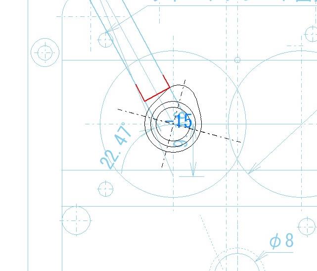
 CAD上でもチェックしました。角あたりします。 CAD上でもチェックしました。角あたりします。帽子上のタペットは構造上セットできません、 仕方がないのでタペット先端を大きな半径を持ったドーム状にすることにしました。 On the cad I can found same problem |
| これで準備万端整いました。 These are the tappets that has completed the finishing process. It now moves very smoothly. |
|
やっと2気筒で回せました。 再始動も問題ありません。 I was finally able to run it with two cylinders. There were no problems with restarting either. |
| 排気管も付けてみました。銅パイプですが… with copper tube exhaust pipe |