![]()
|
2017-6-1 push rod and trouble shooting 1 |
ピストンリング作製が終わったので次はプッシュロッド製作です。
セットしてみないと長さがきっちり決まらないのでこの段階まで待ちました。
I have made new piston rings, now start to push rods.
The length of them was decided under assembled condition.
まず弓鋸でほぼ70㎜に切断。 Now I cut the silver steel wire about 70mm |
この後旋盤にセットして69㎜に長さを調整。 20 push rod Then they were turned to 69mm |
ロッド自体は直径2.5㎜ DXFファイルは長径2.9mm 短径2.7mmで描いています。 これで少し切り込みすぎても円の外周と直線への移行部に段差がつくことを避けやすくなります。 短径を2.5㎜ぴったりにするとちょっとでも刃物が切り込みすぎると段差ができて非常に目立ちます。 きっちりとした円で切削すると以前にも書いたことがありますが、扁平に見えてしまいます。 CNC turning. |
completed |
一番左は試作品、中央が使いやすく作り直したものです。 レンチは貫通穴が開いていてドライバーが通せます。 普通のスパナではロッカーボックス内でナットを回せないので作りました。 Special wrench and driver for adjusting the tappet clearance. Left is test one and center is revised. Wrench has center hole and the driver can penetrates the wrench |
六角レンチはM6 キャップボルトを利用しています。 キャップボルトの流用はModel Engine Builder 誌に以前記事が載っていました。 Hex wrench was made from cap volt |
| used as the picture |
close up view |
| 何と6番シリンダーは圧がゼロ。 7番も0.2MPa位しか出ません。 まいりました。 原因をいろいろ考えました。 1:シリンダヘッドの組み付けが悪い(何しろ3本の固定ボルトですから) 2:バルブでのリーク 3:ピストンリングが悪い 可能性が高い順番にならべました。 バルブのリークは一応チェック済ですし、ほかのシリンダーは同じリングで圧縮が出ています。 I started the compression test after the setting of the push rod. No.6 cylinder shows zero MPa and No.7shows only 0.2 I thought about the reasons 1: leak around the cylinder head because only 3 bolts fixed the head 2: leak around valve 3:leak around the piston ring. Valve leak was already tested and another cylinder shows good compression with same piston rings so possibility of 2 and 3 is low. |
試しにバルブを手で押すと動かない! ひっくり返してみました。 何と排気バルブがライナーに引っ掛かってしまっていました。 I checked the fixation of head but it showed no problem. Then I pushed the valve and found that it could not move. I took off the cylinder and head and found that cylinder liner blocked the valve |
7番はこれで0.6MPa出るようになりましたが 6番は0.2くらいしか出ません。 6番のほうがあたりが強かったので少しバルブに変形が来たのかも。 これからバルブチェックをし直します。 なかなか道のりは遠いですね。 I filed out that portion No.7 shows 0.6MPa but 6 shows only 0.2 The valve in No.6 touched very strong with cylinder liner, probably the valve was distorted. Now I check the valve leak again. |
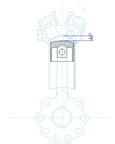
 ちなみに今回のエンジンの圧縮圧は0.6MPaがやっと。 ちなみに今回のエンジンの圧縮圧は0.6MPaがやっと。前のエンジンでは1.6振り切れでした。 少ないので図面でチェックしてみました。 かなりおおざっぱですが ピストン上死点時燃焼室高さは約5.2mm ストロークは28mm 28+5.2/5.2=6.2 圧縮比は6くらい。 0.6MPaは妥当な線のようです。 In compression test this engine shows about 0.6MPa in each cylinder. This figure is smaller than that of previous engines. So I checked the compression ratio on the drawing. The space between cylinder head ceiling and piston head is about 5.2mm And the stroke is 28mm Then the compression ratio is about 6. 0.6 MPa seems to be appropriate. |