![]()
|
2012-5-28 devastating damage 激甚損傷 |
全部組上がりました。後はテストランだけなのですが、オイルポンプの送出量があまりに少ないのが気になります。うまく作動していないで回してしまうと最悪は焼き付きです。
どうしても納得行かずにばらしました。
Assembled. Now on start. But I felt some anxiety on the oil pump.
With the lack of pump activity, the engine will overheat and seize.
I decided to disassemble.
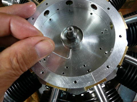 まずチェックしたのはオイルポンプとクランクシャフトのオイル流入部がちゃんと一致しているかどうか。針金を曲げた物で探っています。 まずチェックしたのはオイルポンプとクランクシャフトのオイル流入部がちゃんと一致しているかどうか。針金を曲げた物で探っています。First I checked the oil path with wire. |
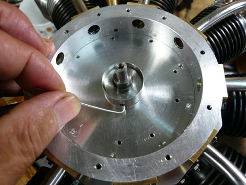 OKでした。ちゃんとクランクシャフトへは連続しています。 OKでした。ちゃんとクランクシャフトへは連続しています。No problem. |
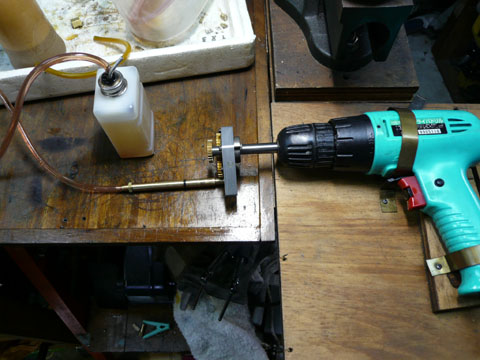 そうなるとポンプの問題。そのままではポンプを駆動できないのでブッシュと軸を作り直して駆動してみました。じゅぶじゅぶ位しか流れません。ポンプに問題があるようです。 そうなるとポンプの問題。そのままではポンプを駆動できないのでブッシュと軸を作り直して駆動してみました。じゅぶじゅぶ位しか流れません。ポンプに問題があるようです。I checked the oil pump itself. I made some parts to drive it. Only a drip by drip, oil came from the pump. I thought that the reason of low flow was in the oil pump. |
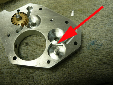 まず気になったのがオイルパスをあけたときに少し削れてしまった部位。ここからオイルが逆流してしまうのではと考えました。 まず気になったのがオイルパスをあけたときに少し削れてしまった部位。ここからオイルが逆流してしまうのではと考えました。First I suspected the groove made by drilling of the oil path. |
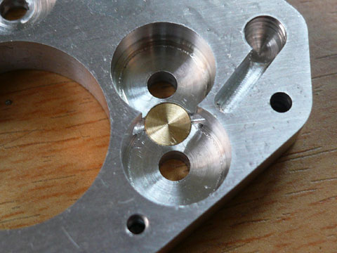 この部分を真鍮丸棒で埋めました。アルミでも良いのですが、真鍮だとロックタイトが非常に早く硬化して結果がすぐ見られます。 この部分を真鍮丸棒で埋めました。アルミでも良いのですが、真鍮だとロックタイトが非常に早く硬化して結果がすぐ見られます。結果は関係無しでした。 I plugged it with brass rod. But it effected nothing. |
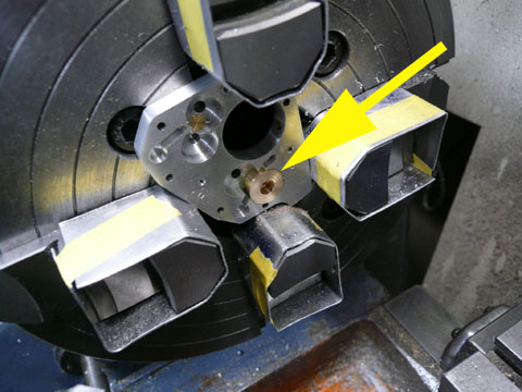 次いで考えたのがポンプ本体とギアーの歯先との隙間。0.1mm近くあります。この部を埋めようとトライしました。そのままでは薄くて物を入れても持ちません。少し拡張してまず砲金のブッシュを入れてロックタイト固定をしました。 次いで考えたのがポンプ本体とギアーの歯先との隙間。0.1mm近くあります。この部を埋めようとトライしました。そのままでは薄くて物を入れても持ちません。少し拡張してまず砲金のブッシュを入れてロックタイト固定をしました。The second I thought about the clearance between the top of the teeth of the gear and side wall. It reached about 0.1mm. I bored up the gear space and plugged with bronze bush |
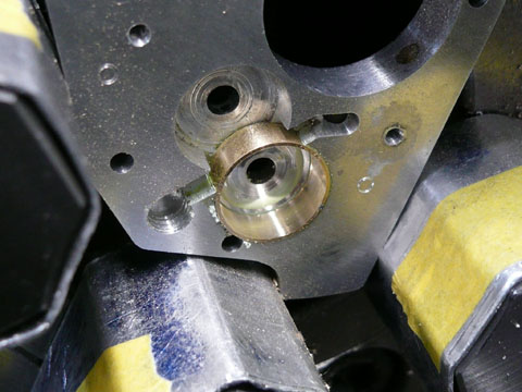 次いでこのブッシュの中ぐりををしてギアースペースを確保しました。ここまでは非常にうまく行きました。 次いでこのブッシュの中ぐりををしてギアースペースを確保しました。ここまでは非常にうまく行きました。Then I bored the space for the gear. It seemed to be good so far. |
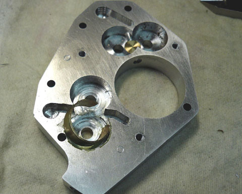 ところが次のスペースに同じ事をするためには今のリングを一部旋削しなければなりません。この段階でリングははずれてしまいました。この方法はこの段階で没となりました。 ところが次のスペースに同じ事をするためには今のリングを一部旋削しなければなりません。この段階でリングははずれてしまいました。この方法はこの段階で没となりました。But when I started to bore up the second gear, the bronze ring was teared. I abandoned this remedy. |
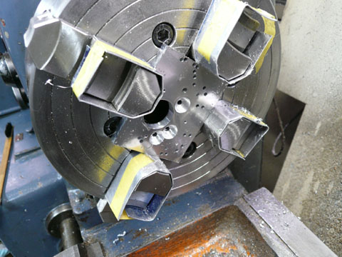 新しい物を作ることにしました。前回はギアースペースをボーリングバーで切削しましたが、より精度を高めないといけないので旋盤にセットしてボーリングしました。非常に注意深く旋削しました。 新しい物を作ることにしました。前回はギアースペースをボーリングバーで切削しましたが、より精度を高めないといけないので旋盤にセットしてボーリングしました。非常に注意深く旋削しました。ちなみにモジュール0.8 15Tの歯車の歯先円直径は協育歯車のカタログでは13.6mmとなっていますが、今回のギアーは摩耗もあるのか13.55mmのスペースに入ってしまいました。 I decided to make new one. In previous one, I bored the gear space with boring head on the mill, but this procedure lacks the accuracy with my home made boring head. I did it on the lathe this time. |
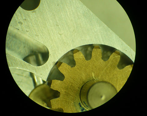 作り直し前のギアースペースです。 作り直し前のギアースペースです。The clearance in previous gear pump. |
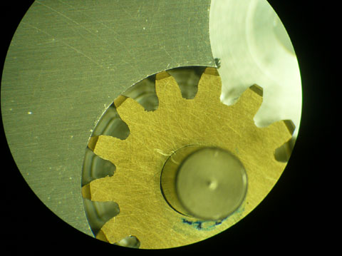 新しく作った物です。非常にタイトに仕上がっていますが、これでもギアーは壁に触れることなくスムースに回ります。これで完璧でしょう。 新しく作った物です。非常にタイトに仕上がっていますが、これでもギアーは壁に触れることなくスムースに回ります。これで完璧でしょう。しかし駆動してみると吐出量は変わりません。ポンプとしてはこんな物のようです。 ちなみに以前エンジン機を飛ばしていた頃使っていた手動のギアーポンプをばらしてみました。(このポンプはぴゅーっと吐出します。) 箱の中は3段のギアー。各段最低で1:5位のギアー比です。3段で125:1。手回しで遅くとも2秒に1回は回します。と言うことは125x30=3750rpm 毎秒一回転だと7500rpm 恐ろしい勢いで駆動されているんですね。 私の使ったドリルはせいぜい500rpm。 何だか無駄な努力をしたようです。 New one. I thought it would be perfect, but when it was driven, the flow was almost same as previous. The performance of the gear pump is like this. By the way I checked the gear pump used in model air plane flying. When I opened the box I found 3 steps of the gear. 5:1 on one step, the rotation comes up to 125 times with handle. We can turn the handle at least one turn in two seconds. The rotation comes up to 3750rpm. My drill turns about 350rpm. The deference of flow in my pump and this pump seemed to be mainly the deference of the number of the rotation. |
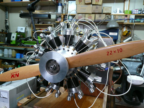 と言うことで組み上がりました。 と言うことで組み上がりました。プロペラは大きいと怖いので22インチを付けました。実際は32インチを用意してあります。 Assembled. |
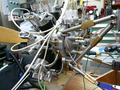 後方から 後方から |
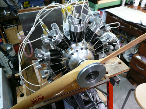 格好だけは整いましたが、当然回りません。 格好だけは整いましたが、当然回りません。 |
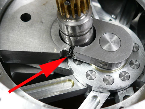 チョークを閉じて、生ガスを吸引。 チョークを閉じて、生ガスを吸引。かなり濃くしておかないと回りません。 30分くらい格闘して、ゴンとノックが来ました。おっ!これでOKと思ったら、クランクシャフトが回りません。クランクシャフトのどこかでピンが抜けてはずれたと思ったのですが・・・・・ あけてびっくり。 なんとクランクシャフトのクランク部が割れてしまっています。しばし呆然。 これからここを太くした図面を引き直して作り直します。一ヶ月はかからないと思うのですが。 Without knocking with hand turn, this type of engine never start, and I felt slightly strong knocking on my hand . I first thought that this engine will start, but the crankshaft rejected to turn. I disassembled and found that crank cheek was cracked. |
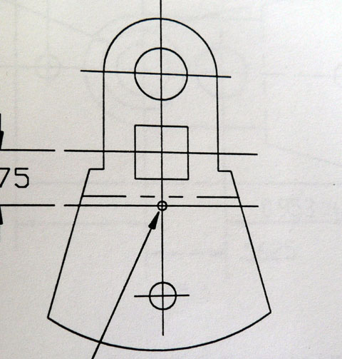 クランク部のかけてしまった原因ですが、オリジナルの図面では角穴にフロント軸を圧入するように指定されています。角穴をあけるブローチも技術もないので丸穴に変更したため割れてしまった部分の肉厚がとれずに割れてしまったようです。原図はよく考えられていると強く印象を受けました。 クランク部のかけてしまった原因ですが、オリジナルの図面では角穴にフロント軸を圧入するように指定されています。角穴をあけるブローチも技術もないので丸穴に変更したため割れてしまった部分の肉厚がとれずに割れてしまったようです。原図はよく考えられていると強く印象を受けました。The original drawing of the crank cheek is like this. I have no broach and technique to bore the square hole, so I arranged it to round hole.For this reason, the cracked portion has not enough thickness. I deeply impressed that original drawings were well considered.. |
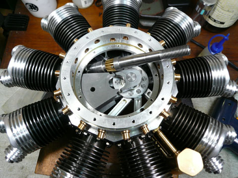 こんな無惨な状態です。 こんな無惨な状態です。気合い!ですね。 テストランは大幅に遅れそうです。 Like this. I will make another strong crankshaft. |