![]()
|
2012-8-10 about my arrangement |
原図からデザイン変更した部分の問題が続出しましたので、この変更について反省点を記載したいと思います。
次から次へとでてくる問題が全部デザイン変更による物で、これを解決するための手段を考え原図を見ると全てこれらが起きないようになっていました。まだまだ未熟なことがよーく分かりました。
I arranged some parts from original design and they caused very serious
problems.
All of these problems were caused by the change from original and I found that original design was perfect
I must examine about these arrangement and problems here.
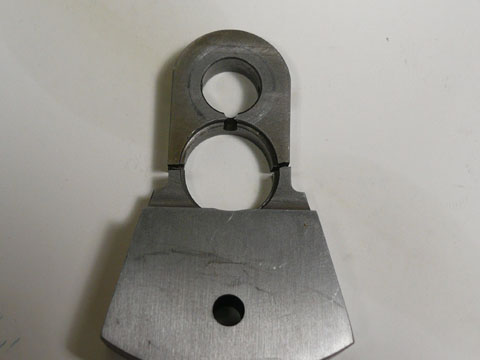 まずクランクウェブ部分の折損。 まずクランクウェブ部分の折損。この部は下の図面を見て分かるように本来は角穴で圧入形式です。 角穴をあけるブローチも技術もないので丸穴にしました。このため肉厚がとれずにノッキングで割れてしまいました。 First, the crack of crank cheek.. In the original design, this part was designed to press fit of square hole. I have no broach and technique, I arranged to use round hole. It caused the thin wall and cracked. |
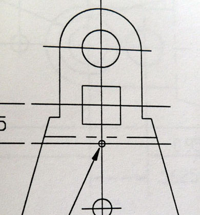 原図ではこうなっています。これだけ肉厚が確保されていれば折損はあり得ないでしょう。作っているときは何も感じずに作りましたが、折れて改めて原図を見て納得しました。 原図ではこうなっています。これだけ肉厚が確保されていれば折損はあり得ないでしょう。作っているときは何も感じずに作りましたが、折れて改めて原図を見て納得しました。In the original, you can find the square hole and thick wall. When I made it, I had no question about it and when found the crack of my crank cheek, I noticed the meaning of the original design. |
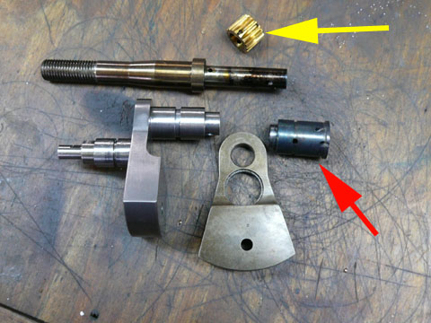 クランクシャフトでも滑りが出て、タイミングがずれてしまうと言う事象が起きました。これもフロント軸を3つの部分に分けて製作したために起きてしまいました。ギアーカットに挑戦せず、既製品を使おうとしたために起きてしまいました。インボリュートカッターの購入までしてあったのでこれでトライすべきだったでしょう。 クランクシャフトでも滑りが出て、タイミングがずれてしまうと言う事象が起きました。これもフロント軸を3つの部分に分けて製作したために起きてしまいました。ギアーカットに挑戦せず、既製品を使おうとしたために起きてしまいました。インボリュートカッターの購入までしてあったのでこれでトライすべきだったでしょう。About the slippage of front journal. I made front journal in 3 parts and Loctited because I am not sure to cut the gear. I had bought the involute cutter already, I had to try it. |
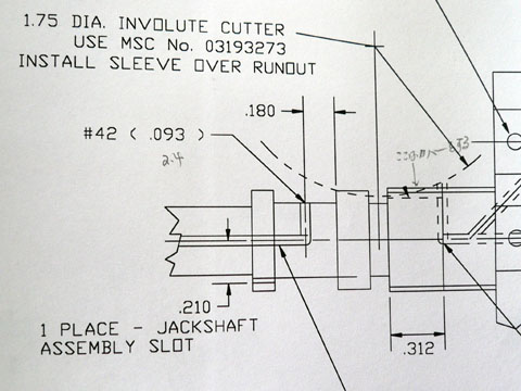 原図では一体として製作し、ギアーはインボリュートカッターで切るようになっています。 原図では一体として製作し、ギアーはインボリュートカッターで切るようになっています。トライすべきだったと反省しています。 In the original design, the gear was cut by involute cutter and made as one piece, there will never be slippage. |
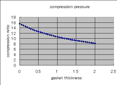 クランクウェブの破損、シャフトでの滑りの一因は高圧縮比に求められます。15を超えてしまうような圧縮比はシリンダーヘッドをアレンジしたために起きてしまいました。 クランクウェブの破損、シャフトでの滑りの一因は高圧縮比に求められます。15を超えてしまうような圧縮比はシリンダーヘッドをアレンジしたために起きてしまいました。The one of the reasons of the crack of crank cheek and front journal slippage is caused by too high compression ratio. It was caused by the change of cylinder head design |
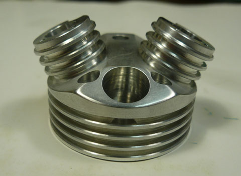 アレンジしたヘッドです。このヘッドに設計変更する時に間違えが生じてしまいました。 アレンジしたヘッドです。このヘッドに設計変更する時に間違えが生じてしまいました。I changed the cylinder head like this. When I changed it into this type I made mistake. |
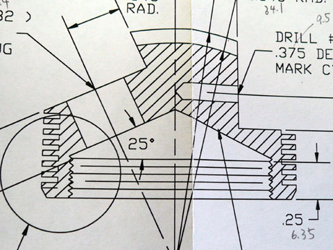 原図ではこのような形でシリンダーにねじ込むようになっています。いったん取り付けたらはずさないことが前提のようです。バルブリークに不安があるためはずせないのは問題かと思い変更しました。またヘッドの形の好みの問題もありました。 原図ではこのような形でシリンダーにねじ込むようになっています。いったん取り付けたらはずさないことが前提のようです。バルブリークに不安があるためはずせないのは問題かと思い変更しました。またヘッドの形の好みの問題もありました。In the original, the cylinder head was screwed on the cylinder. I have not full confidence in my valve, so I selected the bolt fixed type. In this change, I mistook the compression ratio. |
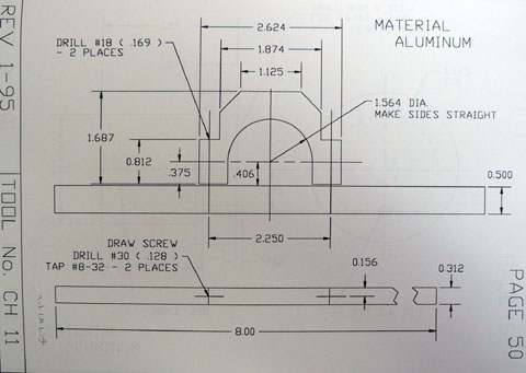 原図ではシリンダーヘッドの締め込み用の道具もちゃんと書かれています。このほか全てのパーツを製作するのに必要なジグや固定具の図面も全て記載されていて、変更さえしなければ至れり尽くせりです。 原図ではシリンダーヘッドの締め込み用の道具もちゃんと書かれています。このほか全てのパーツを製作するのに必要なジグや固定具の図面も全て記載されていて、変更さえしなければ至れり尽くせりです。In the original drawings, there is a drawings of cylinder head tightening wrench. In this set of drawings, there are drawings of all tools and jigs and fixtures for making this engine. It leaves nothing to be desired if you would not make any arrangement! |
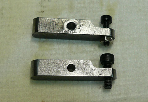 タペット調整ネジもM2では折れてしまました。 タペット調整ネジもM2では折れてしまました。原図ではM2.6(#4-40)を使うようになっていました。ロッカーボックスカバーとの干渉をおそれ細くしましたがこれも失敗。結局図面通りのM2.6に変更しました。 I used M2 screws for tappet adjusting screw and it was thin and weak. In the original drawing, M2.6(#4-40)was used. M2 was broken and I changed it into M2.6. |
| In conclusion. All of my arrangement caused some troubles, so if you try this engine, you should make it according to the original design. If you think about the history of this engine, you can easily reach this conclusion. I first thought that the arrangement might be a easy way but finally it makes some troubles. I could recover from it but to take the original way is safe and confident, I think. 結局私が行ったアレンジはほとんど何らかの不具合を生じてしまいました。 このエンジンをトライしようとするならば、オリジナルの方法を採る方が安全かつ確実かも知れませんね。 とにかくこの図面集は長い歴史を持った、改良に改良を加えられた図面であることは確かです。 |